Does the Terminal Resistance of the CAN Bus Have to be 120Ω?

Learn How The CAN Bus Works (Controller Area Network) | Embedded Systems Explained
| Topics covered in this article: |
| Ⅰ. The role of terminating resistors |
| Ⅱ. Why choose 120Ω? |
| Ⅲ. Why choose 0.25W for power? |
The resistance of the CAN bus terminal is usually 120 ohms. Two 60 ohm resistors are linked in series in the design, and there are usually two 120 ohm nodes on the bus. Basically, persons who are familiar with the CAN bus system. This is common knowledge.
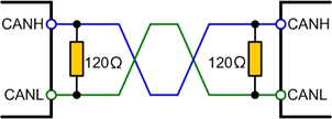
Figure. 1
But, as a scumbag author, I'm well aware that this is a regularly used resistance value in different standards, datasheets, and application notes, but what are the functions of these two terminal resistors? Impedance matching has been discussed previously, but what does matching entail?
The following knowledge points are summarized in this article. In everyday work, knowing the purpose of the terminal resistor might help you locate the source of a problem sooner, such as unstable waveforms.
Ⅰ. The role of terminating resistors
The CAN bus terminal resistor serves three purposes:
Enhance anti-interference performance by allowing high-frequency and low-energy signals to fade away fast.
Ensure that the bus quickly reaches the recessive state, allowing the parasitic capacitance's energy to dissipate more quickly.
Place these at both ends of the bus to reduce reflected radiation and increase signal quality.
01 Improve anti-interference ability
The "dominant" and "recessive" states of the CAN bus are decided by the CAN transceiver. "Dominant" symbolizes "0," "recessive" represents "1." The internal structure of a CAN transceiver is shown in the diagram below, with CAN H and CANL linked to the bus.

Figure. 2
When the bus is dominant, Q1 and Q2 inside the transceiver are turned on, and a pressure difference is generated between CANH and CANL; when the bus is recessive, Q1 and Q2 are turned off, CANH and CANL are in a passive state, and the pressure difference is 0; when the bus is recessive, Q1 and Q2 are turned off, CANH and CANL are in a passive state, and the pressure difference is 0.
When there is no load on the bus, the differential resistance value is very high, and the internal MOS tube is in a high-impedance state. External interference requires very little energy to get the bus to enter dominant mode (the minimum voltage of the common transceiver dominant threshold). (Only 500mV). If there is differential mode interference at this moment, there will be noticeable fluctuations on the bus, and these fluctuations will have no place to absorb them, resulting in the creation of a dominating bit on the bus. As a result, a differential load resistor can be added to increase the anti-interference capabilities of the bus while it is recessive, with the resistance value as low as feasible to avoid the influence of most of the noise energy. However, the resistance should not be too low to avoid requiring too much current from the bus to become dominant.
02 Ensuring fast entry into recessive state
The parasitic capacitances of the bus are charged during the dominant state, and they must be discharged when the bus returns to the recessive state. The capacitor can only be discharged through the differential resistance inside the transceiver if no resistive load is applied between CANH and CANL. This is a significant impedance. The discharge time will be much longer due to the features of the RC filter circuit. To do the simulation test, we connect the transceiver's CANH and CANL with a 220PF capacitor. The bit rate is 500 kilobits per second. The waveform is depicted in the diagram. This waveform's falling edge is a relatively protracted condition.
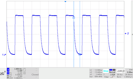
Figure. 3
A load resistor must be connected between CANH and CANL in order to fast discharge the bus parasitic capacitance and ensure that the bus enters the recessive condition. The waveform after adding a 60 ohm resistor is illustrated in the diagram. The duration from dominant recovery to recessive is reduced to 128nS, which is similar to the dominant settling period, as seen in the figure.
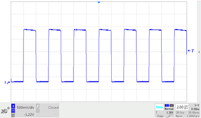
Figure. 4
03 Improve signal quality
Signal reflection occurs when the signal edge energy hits an impedance mismatch at a high slew rate; if the geometry of the transmission cable's cross-section varies, the characteristic impedance of the cable changes as well, resulting in reflections.
The reflected waveform is superimposed on the original waveform when energy is reflected, resulting in ringing.
The quick change in impedance at the bus cable's end generates energy reflection of the signal edge, resulting in ringing on the bus signal. The communication quality will be harmed if the ringing amplitude is too big. At the end of the cable, a terminal resistance equal to the cable's characteristic impedance can absorb this part of the energy and prevent ringing.
The data rate is 1Mbit/s, the transceivers CANH and CANL are connected to a twisted pair of roughly 10m, and the transceiver is terminated with a 120 resistor to assure the recessive conversion time, and the end is not loaded. The signal's waveform near the end is displayed in the picture, and there is a ringing on the signal's rising edge.
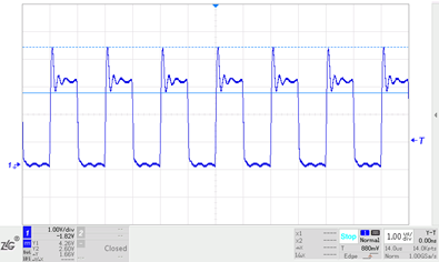
Figure. 5
When a 120 resistance is added to the twisted pair's end, the signal waveform improves dramatically and the ringing disappears.
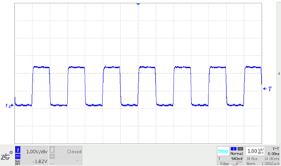
Figure. 6
Because both ends of the cable are the sending and receiving ends in a linear topology, a terminating resistor must be placed at each end of the cable.
The CAN bus is typically a hybrid structure of the bus and the star in the real application process and is not a flawless bus design. It imitates the CAN bus's standard structure.
Ⅱ. Why choose 120Ω?
What exactly is impedance? The resistance to the current in a circuit is known as impedance in electrical. The ohm is the unit of impedance, which is commonly written as Z, which is a complex number Z= R+i(L–1/(C)). Impedance is separated into two parts: resistance (the real part) and reactance (the hypothetical part) (imaginary part). Capacitive and inductive reactances are included in the reactance. Capacitive reactance is the current obstruction produced by capacitance, while inductive reactance is the current obstruction caused by inductance. The term "impedance" relates to the Z mode.
Any cable's characteristic impedance can be determined experimentally. The cable is linked to a square wave generator on one end and an adjustable resistor on the other, with the waveform on the resistor being examined using an oscilloscope. Adjust the resistor's resistance value until the signal on the resistor is a good square wave with no ringing, and the resistance value is compatible with the cable's characteristic impedance at this point.
The characteristic impedance may be determined using two normal automotive cables and twisting them into twisted pairs using the above approach, which is about 120, which is also the resistance value of the terminal resistance recommended by the CAN standard, therefore this 120 is measured. It is not calculated; rather, it is calculated depending on the features of the real wiring harness. Of course, the ISO 11898-2 standard defines it as well.

Figure. 7
Ⅲ. Why choose 0.25W for power?
This must be calculated in conjunction with a number of fault conditions. The short-circuit to the power supply and the short-circuit to the ground must be considered in all interfaces of the automobile ECU, so we must also consider the short-circuit of the CAN bus node to the power supply, as well as the short-circuit to 18V, as required by the standard. The current will flow to CANL through the terminating resistor if CANH is short-circuited to 18V, and the maximum injection current inside CANL is 50mA (indicated in the TJA1145) due to current limiting, and the power of the 120 resistor is 50mA at this moment. *50mA*120Ω=0.3W. The terminal resistor has a power of 0.5W while derating at high temperatures.
1. What is the meaning of CAN bus?
The meaning of CAN bus is the abbreviation of Controller Area Network (CAN), which is an ISO international standardized serial communication protocol. It is one of the most widely used field buses in the world. Initially, CAN was designed as a microcontroller communication in the automotive environment, exchanging information between the electronic control devices in the vehicle to form an automotive electronic control network.
2. Is the CAN bus full duplex or half duplex? Can I send and receive data at the same time?
Half-duplex, can receive data at the same time, but cannot send data at the same time.
3. How to connect the CAN bus?
The positive pole of the power supply of the equipment is connected to the constant electricity on the car (the constant electricity refers to the wiring harness that has the power supply when the main battery switch is turned on); the negative pole of the power supply is used to connect the negative pole of the car battery, and the ACC is connected to the power supply of the ACC gear of the car key.
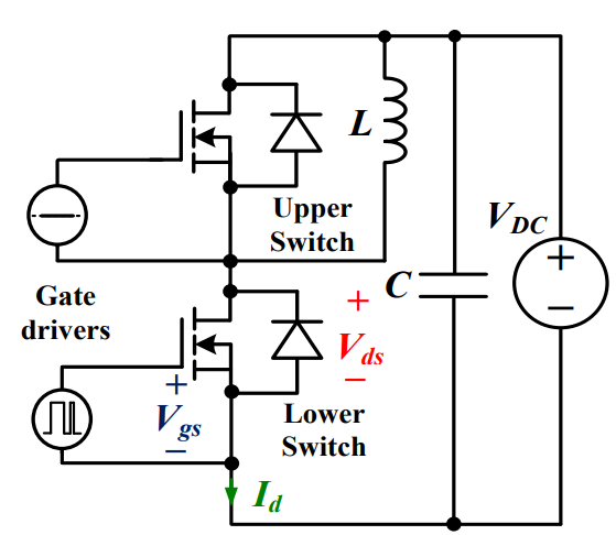 Discovering New and Advanced Methodology for Determining the Dynamic Characterization of Wide Bandgap DevicesSaumitra Jagdale15 March 20242346
For a long era, silicon has stood out as the primary material for fabricating electronic devices due to its affordability, moderate efficiency, and performance capabilities. Despite its widespread use, silicon faces several limitations that render it unsuitable for applications involving high power and elevated temperatures. As technological advancements continue and the industry demands enhanced efficiency from devices, these limitations become increasingly vivid. In the quest for electronic devices that are more potent, efficient, and compact, wide bandgap materials are emerging as a dominant player. Their superiority over silicon in crucial aspects such as efficiency, higher junction temperatures, power density, thinner drift regions, and faster switching speeds positions them as the preferred materials for the future of power electronics.
Read More A Comprehensive Guide to FPGA Development BoardsUTMEL11 September 20257980
This comprehensive guide will take you on a journey through the fascinating world of FPGA development boards. We’ll explore what they are, how they differ from microcontrollers, and most importantly, how to choose the perfect board for your needs. Whether you’re a seasoned engineer or a curious hobbyist, prepare to unlock new possibilities in hardware design and accelerate your projects. We’ll cover everything from budget-friendly options to specialized boards for image processing, delve into popular learning paths, and even provide insights into essential software like Vivado. By the end of this article, you’ll have a clear roadmap to navigate the FPGA landscape and make informed decisions for your next groundbreaking endeavor.
Read More Applications of FPGAs in Artificial Intelligence: A Comprehensive GuideUTMEL29 August 20252199
This comprehensive guide explores FPGAs as powerful AI accelerators that offer distinct advantages over traditional GPUs and CPUs. FPGAs provide reconfigurable hardware that can be customized for specific AI workloads, delivering superior energy efficiency, ultra-low latency, and deterministic performance—particularly valuable for edge AI applications. While GPUs excel at parallel processing for training, FPGAs shine in inference tasks through their adaptability and power optimization. The document covers practical implementation challenges, including development complexity and resource constraints, while highlighting solutions like High-Level Synthesis tools and vendor-specific AI development suites from Intel and AMD/Xilinx. Real-world applications span telecommunications, healthcare, autonomous vehicles, and financial services, demonstrating FPGAs' versatility in mission-critical systems requiring real-time processing and minimal power consumption.
Read More 800G Optical Transceivers: The Guide for AI Data CentersUTMEL24 December 20251028
The complete guide to 800G Optical Transceiver standards (QSFP-DD vs. OSFP). Overcome supply shortages and scale your AI data center with Utmel Electronic.
Read More Xilinx FPGAs: From Getting Started to Advanced Application DevelopmentUTMEL09 September 20252889
This guide is your comprehensive roadmap to understanding and mastering the world of Xilinx FPGA technology. From selecting your first board to deploying advanced AI applications, we'll cover everything you need to know to unlock the potential of these remarkable devices. The global FPGA market is on a significant growth trajectory, expected to expand from USD 8.37 billion in 2025 to USD 17.53 billion by 2035. This surge is fueled by the relentless demand for high-performance, adaptable computing in everything from 5G networks and data centers to autonomous vehicles and the Internet of Things (IoT). This guide will walk you through the key concepts, tools, and products in the Xilinx ecosystem, ensuring you're well-equipped to be a part of this technological revolution.
Read More
Subscribe to Utmel !
![AT88SC25616C-PU]() AT88SC25616C-PU
AT88SC25616C-PUMicrochip Technology
![FM3164-G]() FM3164-G
FM3164-GCypress Semiconductor Corp
![HCS301-I/P]() HCS301-I/P
HCS301-I/PMicrochip Technology
![L9660TR]() L9660TR
L9660TRSTMicroelectronics
![MOC3062VM]() MOC3062VM
MOC3062VMON Semiconductor
![MOC3020SR2M]() MOC3020SR2M
MOC3020SR2MON Semiconductor
![FGBS3040E1-F085]() FGBS3040E1-F085
FGBS3040E1-F085ON Semiconductor
![ATSHA204-TSU-T]() ATSHA204-TSU-T
ATSHA204-TSU-TMicrochip Technology
![AD8196ACPZ]() AD8196ACPZ
AD8196ACPZAnalog Devices Inc.
![TLE8110EDXUMA1]() TLE8110EDXUMA1
TLE8110EDXUMA1Infineon Technologies


